RVfpga System
SweRV EH1 Core
- open surce.
- by Western Digital.
- 2-way superscalar. It can execute multiple instructions per clock cycle, in parallel, by using multiple execution units.
- 9-stage pipeline.
- in-order.
- RV32IMC.
- Separate instruction and data memories (ICCM and DCCM) tightly coupled to the core.
- 4-way set-associative I$ (instruction cache) with parity or ECC protection.
- Programmable interrupt controller.
- Core debug unit compliant with RISC-V debug specification.
- system bus: AXI4 or AHB-Lite.
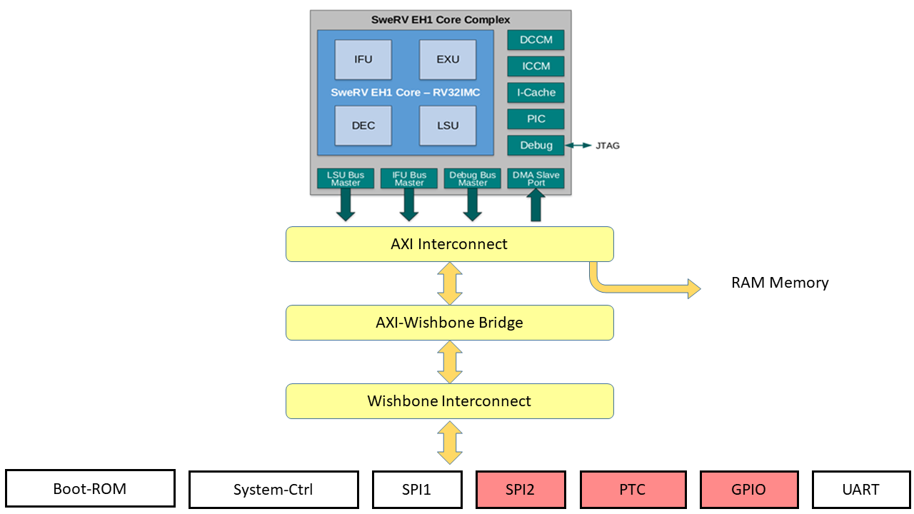
SweRVolf SoC
- From Chips Alliance.
- Boot ROM, UART, System Controller, and an SPI controller (SPI1)
- Renamed to VeeRwolf.
SweRVolfX
- Extended with peripherals: another SPI controller (SPI2), a GPIO, 8-digit 7-segment displays and a PTC.
- SweRV EH1 uses an AXI bus. Peripherals use a Wishbone bus. So the SoC has an AXI to Wishbone bridge.
RVfpga Nexys
- SweRVolfX targeted to Nexys A7 FPGA board
- on-board memory, lite DRAM controller
- clock generator
- clock domain
- bscan logic for the JTAG port.
- Peripherals: DDR2 memory, UART via USB, SPI memory flash, 16 leds and switches, SPI accelerometer, 8 digit 7-segment displays.
RVfpga Sim
- targeted for simulation.
- wrapped in a testbench to be used by Verilator, an HDL simulator.
I’m running this in an Ubuntu 22.04 virtual machine because all the other options to run it from my Debian unstable where a mess.
Installation
-
Download https://cm.lf.training/LFD119x/
username: LFtraining
password: Penguin2014This includes an Ubuntu 22.04 virtual machine for virtual box.
user and password: rvfpga -
Install vscode.
-
Install python3 utilities:
$ sudo apt install python3-distutils python3-venv -
In vscode, install the PlatformIO extension.
-
In the PlatformIO extension, go to
PIO Home > Open. -
Go to
Platforms > Embedded. -
Install the CHIPS Alliance platform.
RVfpga-ViDBo
-
$ sudo apt install libwebsockets-dev -
In vscode, open the folder
Chapters/01/LedsSwitches_C-Lang. Trust the authors.
This project reads the values of the switches in the simulated board and writes them in the corresponding LED. -
Open the file
platformio.iniand fix the path to ViDBo in the variableboard_debug.verilator.binary. -
Go to PlatformIO ant logo, and click
PROJECT TASKS > swervolf_nexys > Platform > RVfpga-ViDBo/Pipeline. -
Run the python server:
$ cd RVfpga_v2/Simulators/verilatorSIM_ViDBo/ $ python3 -m http.server --directory NexysA7board/ -
Open http://localhost:8000/nexys-a7.html, click Connect to board, and test the switches.
RVfpga-Pipeline Simulator
-
In vscode, open the folder
Chapters/01/AL_Operations. Trust the authors.
This is a very simple assembly program with three operations in an infinite loop. -
Open the file
platformio.iniand fix the path to the simulator in the variableboard_debug.verilator.binary. -
Add
and zero, t4, t5before the loop in thesrc/AL_Operations.Sfile.
This is a control instruction of the simulator used as execution breakpoint. -
Go to PlatformIO ant logo, and click
PROJECT TASKS > swervolf_nexys > Platform > RVfpga-ViDBo/Pipeline. -
On the simulation window, click the +1 cycle a few times.
RVfpga-Trace
-
Install gtkwave
$ sudo apt install gtkwave -
In
src/AL_Operations.Sremove the control instruction. -
Open the file
platformio.iniand fix the path to the tracer in the variableboard_debug.verilator.binary. -
Go to PlatformIO ant logo, and click
PROJECT TASKS > swervolf_nexys > Platform > Generate Trace. The trace is generated inChapters/01/AL_Operations/.pio/build/swervolf_nexys/trace.vcd`. -
Open the trace file with
gtktrace. -
In
gtktrace, go toFile > Read Tcl Script Fileand selectChapters/01/AL_Operations/test.tcl. -
Zoom in and advance the clock.
RVfpga-Whisper
A RISC-V instruction set simulator.
-
Open the file
platformio.iniand uncomment line #17 to set whisper as the debug tool. -
Clich the Run and Debug button in the sidebar.
-
Click the play
PIO Debugbutton. -
Step through the code with the debug buttons, observing the
t3register in the left panel.
RISC-V calling convention
Part of the Application Binary Interface (ABI).
The jump and link instruction (jal) invokes a call to a function.
jal function
Jumps to the label function and saves the address of the instruction after jal into the return address register (ra = x1). The function then returns by using the return (ret) pseudo-instruction (or jump register instruction: jr ra).
Input arguments are passed to the function in registers a0–a7. If additional arguments are needed, they are placed on the stack. Return values are placed in registers a0 and a1.
It is essential that the function preserves the contents of those registers that can be seen by the programmer. For every function to create a temporary copy in memory of all those registers that will be modified, and to restore their original values before returning to the caller program. This solution is implemented by means of the call stack, which is a memory region that is accessed using a LIFO (Last-In-First-Out) policy, used to store all the information related to those functions that have started, but not finished their execution. It begins at the end of the available memory, in the higher addresses, and grows towards lower addresses.
A function is normally structured into three parts:
- Entry code, Prologue
- Function, Body
- Exit code, Epilogue
The Prologue must create the function’s stack frame and store registers on the stack, if needed. The stack frame is the memory region used by a function during its execution. The Epilogue restores the architectural state of the caller program and releases the memory space occupied by the stack frame, thus leaving the stack exactly as it was before executing the Prologue.
Accesses to the stack are managed by the stack pointer (sp = x2), which stores the address of the last occupied location of the stack. Before a program begins, sp must be initialized with the address of the base of the stack (i.e. the highest address of the stack region).
The frame pointer (fp = x8) points to the base address (i.e. the highest address) of the active function’s stack frame.
In addition to the stack pointer (sp) and return address register (ra), twelve integer registers s0–s11 are preserved across calls and must be saved by the callee if used by it.
Some registers need not be preserved by the callee and, thus, could be lost after the call. In addition to the argument and return value registers (a0–a7), t0–t6 are temporary registers that are volatile across calls and must be saved by the caller if used again after the function invocation.
The stack expands as more memory is needed by functions’ stack frames and contracts as those functions complete. The stack grows downwards (towards lower addresses) and the stack pointer shall be aligned to a 16-byte boundary upon procedure entry. The stack pointer must remain aligned throughout procedure execution.