Digital logic
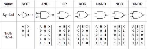
Logic gates
A wire carries a boolean value, where high and low voltages can be viewed as 1 or 0.
TL-Verilog
| not | ! or ~ |
| and | & or && |
| or | ` |
| xor | ^ |
Signal names are prefixed with $.
Vectors:
$vect[7:0] = 8'd6;
$vect[7:0] = 8'b110
$vect[7:0] = 8'h6
Concatenation: $word[15:0] = {$upper_byte, $lower_byte};
Multiplexer: $out = $sel ? $in1 : $in0;
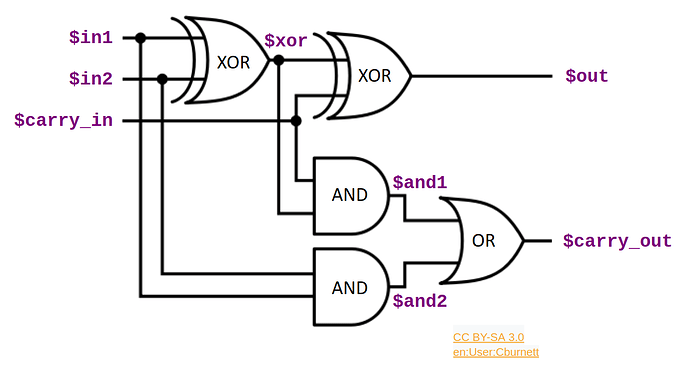
Full adder circuit
$xor = $in1 ^ $in2;
$out = $xor ^ $carry_in;
$and1 = $carry_in && $xor;
$and2 = $in2 && $xor;
$carry_out = $and1 || $and2;
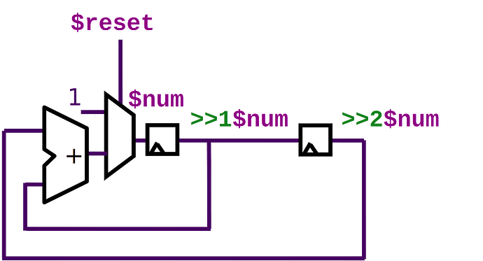
Flip flop:
Fibonacci: $num[31:0] = $reset ? 1 : (>>1$num + >>2$num);
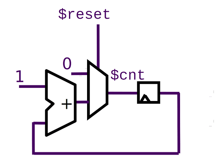
Counter:
$cnt[15:0] = $reset ? 16'b0 : >>1$cnt + 1;
RISC-V implementation
Link the reset signal.
$reset = *reset;
Program counter (PC)
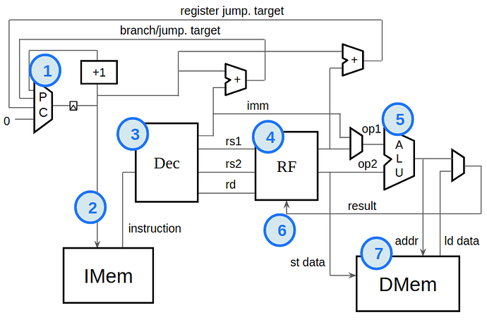
Identifies the instruction the CPU will execute next. The default behavior is to increment to the following instruction each clock cycle. Branch and jump are not sequential, they specify a target to execute next.
The PC is a byte address referencing the first byte of an instruction in IMEM. Instructions are 4 bytes long. The lowest two PC bits must always be zero.
$pc[31:0] = >>1$next_pc[31:0];
$next_pc[31:0] = $reset ? 32'b0 : $pc + 32'd4;
Instruction memory (IMEM)
Holds the instructions to execute. We pull the instruction pointed by the PC.
A verilog macro:
`READONLY_MEM($pc, $$instr[31:0]);
Decode
Break the instruction into fields based on its type.
$is_r_instr = $instr[6:2] == 5'b01011 ||
   $instr[6:2] == 5'b01100 ||
   $instr[6:2] == 5'b01110 ||
   $instr[6:2] == 5'b10100;
$is_i_instr = $instr[6:2] == 5'b00000 ||
   $instr[6:2] == 5'b00001 ||
   $instr[6:2] == 5'b00100 ||
   $instr[6:2] == 5'b11001;
$is_s_instr = $instr[6:2] ==? 5'b0100x;
$is_b_instr = $instr[6:2] == 5'b11000;
$is_u_instr = $instr[6:2] ==? 5'b0x101;
$is_j_instr = $instr[6:2] == 5'b11011;

$opcode[6:0] = $instr[6:0];
$func3_valid = $is_r_instr || $is_i_instr || $is_s_instr || $is_b_instr;
$funct3[2:0] = $instr[14:12];
$func7_valid = $is_r_instr;
$func7[6:0] = $instr[31:25];
$rs1_valid = $is_r_instr || $is_i_instr || $is_s_instr || $is_b_instr;
$rs1[4:0] = $instr[19:15];
$rs2_valid = $is_r_instr  || $is_s_instr || $is_b_instr;
$rs2[4:0] = $instr[24:20];
$rd_valid = $is_r_instr || $is_i_instr || $is_u_instr || $is_j_instr;
$rd[4:0] = $instr[11:7];
$imm_valid = $is_i_instr || $is_s_instr || $is_b_instr || $is_u_instr || $is_j_instr;
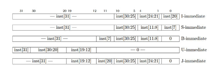
$imm[31:0] = $is_i_instr ? {  {21{$instr[31]}},  $instr[30:20]  } :
   $is_s_instr ? { {21{$instr[31]}}, $instr[30:25], $instr[11:8], $instr[7] } :
   $is_b_instr ? { {20{$instr[31]}}, $instr[7], $instr[30:25], $instr[11:8], 1'b0 } :
   $is_u_instr ? { $instr[31:12], 12'b0} :
   $is_j_instr ? { {12{$instr[31]}}, $instr[19:12], $instr[20], $instr[30:21], 1'b0 } :
   32'b0;
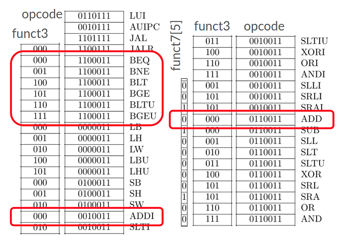
$dec_bits[10:0] = {$instr[30], $funct3, $opcode};
$is_beq = $dec_bits ==? 11'bx_000_1100011;
$is_bne = $dec_bits ==? 11'bx_001_1100011;
$is_blt = $dec_bits ==? 11'bx_100_1100011;
$is_bge = $dec_bits ==? 11'bx_101_1100011;
$is_bltu = $dec_bits ==? 11'bx_110_1100011;
$is_bgeu = $dec_bits ==? 11'bx_111_1100011;
$is_addi = $dec_bits ==? 11'bx_000_0010011;
$is_add = $dec_bits ==? 11'b0_000_0110011;
Register file read
A small local storage of values the program is actively working with.
$rd_en1 = $rs1_valid;
$rd_index1[4:0] = $rs1;
$rd_en2 = $rs2_valid;
$rd_index2[4:0] = $rs2;

m4+rf(32, 32, $reset, $wr_en, $wr_index[4:0], $wr_data[31:0], $rd_en1, $rd_index1[4:0], $src1_value, $rd_en2, $rd_index2[4:0], $src2_value)
Arithmetic logic unit
It computes for each possible instruction, the result it would prodece. It then selects based on the actual instruction, which of these results is the correct one.
$result[31:0] =
   $is_addi ? $src1_value + $imm :
   $is_add ? $src1_value + $src2_value :
   32'b0;
Register file write
$wr_en = $rd == 5'b0 ? 0 : $rd_valid;
$wr_index[4:0] = $rd;
$wr_data[31:0] = $result;
Branch logic
A condition branch instruction will branch to a target PC if its condition is true. Conditions are comparison of the two source registers.
$taken_br =
   $is_beq ? $src1_value == $src2_value :
   $is_bne ? $src1_value != $src2_value :
   $is_blt ? ($src1_value < $src2_value) ^ ($src1_value[31] != $src2_value[31]) :
   $is_bge ? ($src1_value >= $src2_value) ^ ($src1_value[31] != $src2_value[31]) :
   $is_bltu ? $src1_value < $src2_value :
   $is_bgeu ? $src1_value >= $src2_value :
   0;
Update the PC:
$br_tgt_pc[31:0] = $pc + $imm;
$pc[31:0] = >>1$next_pc[31:0];
$next_pc[31:0] = $reset ? 32'b0 :
   $taken_br ? $br_tgt_pc :
   $pc + 32'd4;
Enable the passed check, replacing the line with passed with:
m4+tb()
Completing the RISC-V CPU
Use this macro as test program, replacing the commented out code in the \SV section:
m4_test_prog()
Finish the decode logic. Load and store operations are all handled the same.
$is_lui = $dec_bits ==? 11'bx_xxx_0110111;
$is_auipc = $dec_bits ==? 11'bx_xxx_0010111;
$is_jal = $dec_bits ==? 11'bx_xxx_1101111;
$is_jalr = $dec_bits ==? 11'bx_000_1100111;
$is_beq = $dec_bits ==? 11'bx_000_1100011;
$is_bne = $dec_bits ==? 11'bx_001_1100011;
$is_blt = $dec_bits ==? 11'bx_100_1100011;
$is_bge = $dec_bits ==? 11'bx_101_1100011;
$is_bltu = $dec_bits ==? 11'bx_110_1100011;
$is_bgeu = $dec_bits ==? 11'bx_111_1100011;

$is_load = $dec_bits ==? 11'bx_xxx_0000011;
$is_store = $is_s_instr;

$is_addi = $dec_bits ==? 11'bx_000_0010011;
$is_slti = $dec_bits ==? 11'bx_010_0010011;
$is_sltiu = $dec_bits ==? 11'bx_011_0010011;
$is_xori = $dec_bits ==? 11'bx_100_0010011;
$is_ori = $dec_bits ==? 11'bx_110_0010011;
$is_andi = $dec_bits ==? 11'bx_111_0010011;
$is_slli = $dec_bits ==? 11'b0_001_0010011;
$is_srli = $dec_bits ==? 11'b0_101_0010011;
$is_srai = $dec_bits ==? 11'b1_101_0010011;
$is_add = $dec_bits ==? 11'b0_000_0110011;
$is_sub = $dec_bits ==? 11'b1_000_0110011;
$is_sll = $dec_bits ==? 11'b0_001_0110011;
$is_slt = $dec_bits ==? 11'b0_010_0110011;
$is_sltu = $dec_bits ==? 11'b0_011_0110011;
$is_xor = $dec_bits ==? 11'b0_100_0110011;
$is_srl = $dec_bits ==? 11'b0_101_0110011;
$is_sra = $dec_bits ==? 11'b1_101_0110011;
$is_or = $dec_bits ==? 11'b0_110_0110011;
$is_and = $dec_bits ==? 11'b0_111_0110011;
Finish the implementation of the arithmetic logic unit:
// Set if less than, unsigned.
$sltu_rslt[31:0] = {31'b0, $src1_value < $src2_value};
// Set if less than immediate, unsigned.
$sltiu_rslt[31:0] = {31'b0, $src1_value < $imm};

// Shift right, arithmetic.
// sign-extended src1.
$sext_src1[63:0] = { {32{$src1_value[31]}}, $src1_value };
// 64-bit sign-extended results, to be truncated.
$sra_rslt[63:0] = $sext_src1 >> $src2_value[4:0];
$srai_rslt[63:0] = $sext_src1 >> $imm[4:0];

$result[31:0] =
   $is_andi ? $src1_value & $imm :
   $is_ori ? $src1_value | $imm :
   $is_xori ? $src1_value ^ $imm :
   ($is_addi || $is_load || $is_store) ? $src1_value + $imm :
   $is_slli ? $src1_value << $imm[5:0] :
   $is_srli ? $src1_value >> $imm[5:0] :
   $is_and ? $src1_value & $src2_value :
   $is_or ? $src1_value | $src2_value :
   $is_xor ? $src1_value ^ $src2_value :
   $is_add ? $src1_value + $src2_value :
   $is_sub ? $src1_value - $src2_value :
   $is_sll ? $src1_value << $src2_value[4:0] :
   $is_srl ? $src1_value >> $src2_value[4:0] :
   $is_sltu ? $sltu_rslt :
   $is_sltiu ? $sltiu_rslt :
   $is_lui ? {$imm[31:12], 12'b0} :
   $is_auipc ? $pc + $imm :
   $is_jal ? $pc + 32'd4 :
   $is_jalr ? $pc + 32'd4 :
   $is_slt ? ( ($src1_value[31] == $src2_value[31]) ?
      $sltu_rslt :
      {31'b0, $src1_value[31]} ) :
   $is_slti ? ( ($src1_value[31] == $imm[31]) ?
      $sltiu_rslt :
      {31'b0, $src1_value[31]} ) :
   $is_sra ? $sra_rslt[31:0] :
   $is_srai ? $srai_rslt[31:0] :
   32'b0;
Finish implementing jump logic:
$jalr_tgt_pc[31:0] = $src1_value + $imm;
Update next PC:
$next_pc[31:0] = $reset ? 32'b0 :
   ($taken_br || $is_jal) ? $br_tgt_pc :
   $is_jalr ? $jalr_tgt_pc :
   $pc + 32'd4;
For memory load and store, assume they all operate in words.
Use the arithmetic result to calculate the address, extending the ADDI case:
($is_addi || $is_load || $is_store) ? $src1_value + $imm :
Uncomment the dmem macro and connect the arguments:
m4+dmem(32, 32, $reset, $result[6:2], $is_store, $src2_value, $is_load, $ld_data)
Update the value to write to the register in case the instruction is load:
$wr_data[31:0] = $is_load ? $ld_data : $result;
